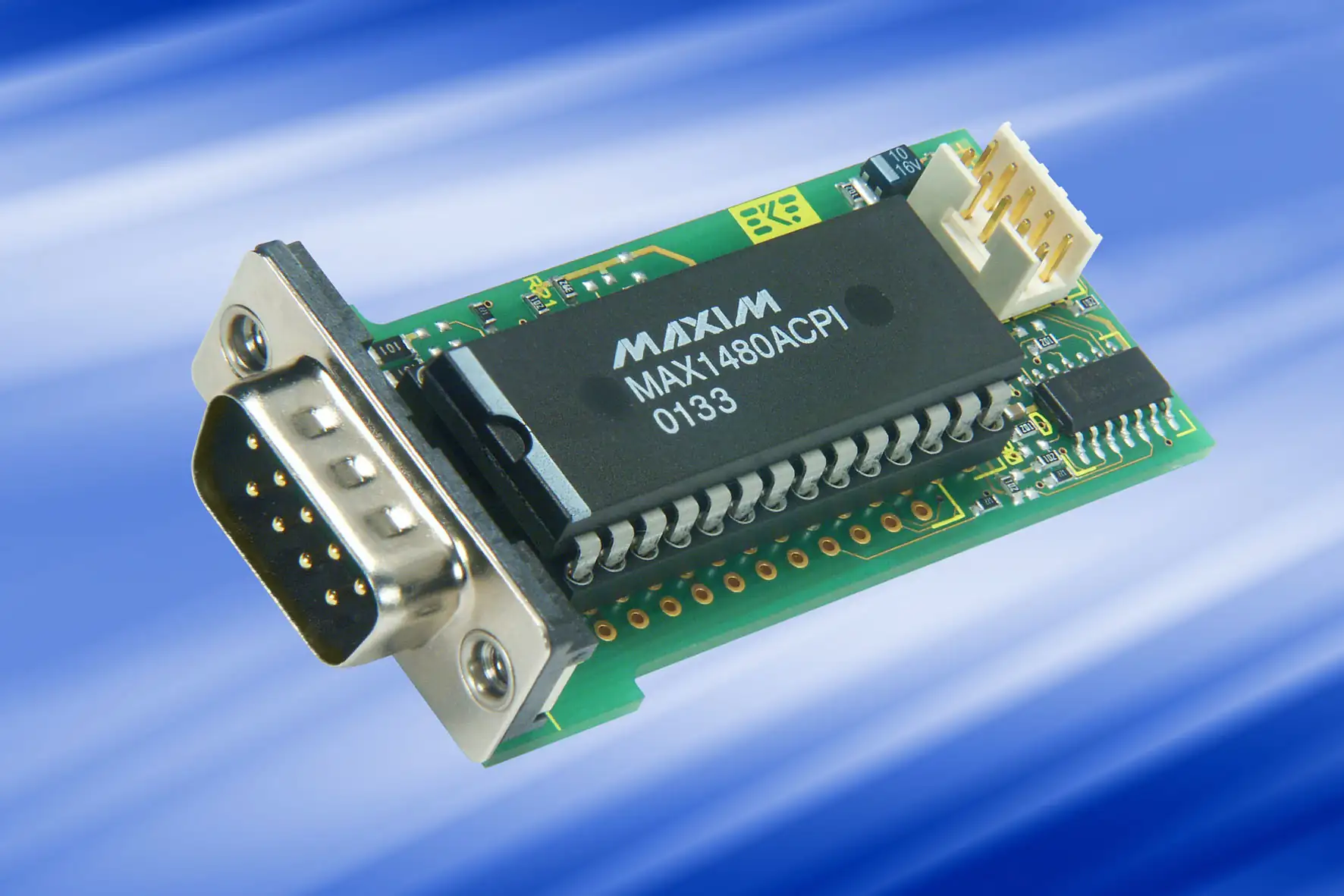
CU7-RS485
Isolated RS-485 Rear-I/O Module
The CU7-RS485 is a rear-I/O PHY module, destined for CompactPCI® systems, to be used in combination with the serial interface cards CU1-CHORUS and CU2-QUARTET. The CU7-RS485 is provided with an electrically isolated TIA-485 data transceiver for EMI sensitive applications.
More often known as RS-485, this standard is a popular balanced voltage signal technology for interconnecting devices on an industrial network, up to 1200m cable length. The CU7-1-RS485 allows for connecting various controllers in a daisy-chain fashion across a single twisted pair cable, while the CU7-2-RS485 is suitable for a direct point-to-point interconnection between two devices over a 4-wire line.
Designed for harsh environment, the CU7-RS485 modules are high-reliability, rugged RS-485 interfaces, well suited for industrial and telecommunication purposes.
The RS-485 bus network topology is also known as party-line. Using a half-duplex transmission principle, this method requires a single twisted pair cable only, by way of connecting together driver outputs and receiver inputs. The CU7-1-RS485 allows for up to 32 networking nodes, sharing a common bus. Typically, all devices receive all messages permanently, but there is only one sender allowed to be enabled at a given time.
Point-to-point interconnections however can be established as a full-duplex 4-wire line (sending and receiving data simultaneously). The CU7-2-RS485 is therefore equipped with separated drivers and receivers.
While providing data transfer rates up to 2.5Mbps, both modules are protected against ESD up to 15kV and electrically isolated up to 500V. The CU7-1-RS485 and CU7-2-RS485 modules are intended for use especially with the serial interface board CU4-SOPRANO. This CompactPCI® card has its TTL level serial ports routed to J2 for rear I/O by additional PHY (physical layer) modules.
Mounted onto the CPCI backplane from behind, the additional distribution board CU9-BASE for up to 16 ports is equipped with metric 2mm pin headers, mating the flat ribbon cable assemblies to the particular PHY modules such as the CU7-RS485.
As data rates increase, proper termination on both ends of the RS-485 bus becomes important. A popular approach is to use external termination, having the resistors located within the shell of the DB9 connectors.
As an alternative, termination resistors can be stuffed directly on the CU7-RS485 board. Due to miniaturized SMD components, a properly equipped working place is highly recommended.
Typically, the termination resistor value is 120 Ohm or 130 Ohm, ideally matching the twisted pair cable impedance. When calculating, the optionally stuffed bias resistors for open-line fail-safe termination would lie in parallel. Normally, this effect can be disregarded.
Any party-line network must be terminated at the extreme ends of its bus. Stubs in order to attach particular nodes are not allowed.
When establishing a point-to-point full-duplex interconnection, both data directions, receiver and driver lines, require termination. This means, in addition to the A/B line also the Y/Z line must be terminated.
The RS-485 receivers used in the MAX1480/MAX1490 have an internal built-in fail-safe feature, so that the resistors R17/R18 and R22/R23 (see figure below) normally should not be stuffed. If for some reason bias resistors for open-line fail-safe termination are required, a nominal value of 750 Ohm or 820 Ohm is recommended.
Downloads & Ressources
Documents
Specifications
- Rear-I/O Module (60x31mm2)
Simplified Block Diagram
